鑫景福致力于满足“高品质”PCBA订购单需求。


Process requirements and precautions for SMT processing
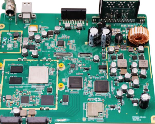
EffICiency SMT patch processing has many aspects For example, if the total output is unchanged, the SMT chip production line has a large number, and the production speed can also be improved However, operating costs are also increasing Nowadays, the fierce competition in the electronic industry is unimaginable In the case of existing production lines, it is crucial to improve the placement rate and win customer satisfaction
Features: The processing precision of the chip is not high, and the number of components is SMAll. The components are mainly resistors and capacitors, or there are individual special-shaped components.
Key processes:
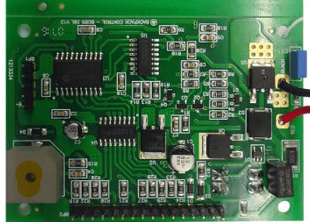
2. SMT processing during placement: Generally, manual placement can be used, and single components with higher position accuracy can also be placed by manual placement machine
3. Welding: Reflow welding is generally adopted, and spot welding can also be adopted under special circumstances.
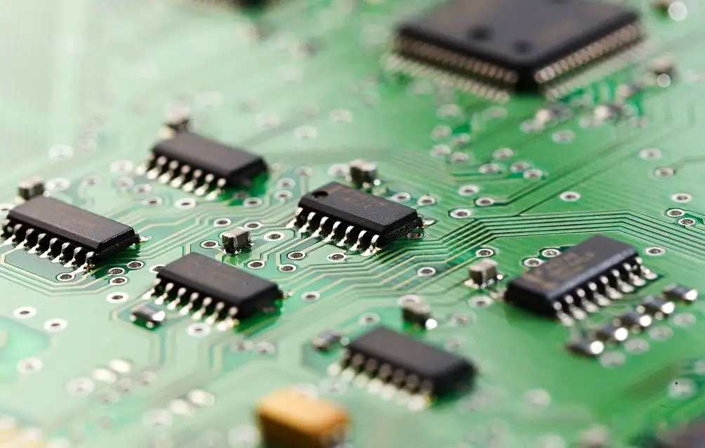
High precision placement in SMT processing
Features: The FPC must have the positioning MARK of the base plate, and the FPC itself must be flat. In large-scale production, it is difficult to fix FPCs and ensure consistency, which requires high equipment. In addition, it is difficult to control the printing paste and placement process.
Key processes: 1. FPC fixation: fixed on the tray from printing patch to reflow soldering. The pallet used requires a smaller coefficient of thermal expansion. There are two fixing methods, and the placement accuracy is QFP lead spacing 0. Use this method when 65MM or larger
A. When the placement accuracy is QFP guide spacing 0. 65MM or less
B Method A: Set the pallet on the positioning template. FPC is fixed on the tray with a thin high temperature resistant adhesive tape, and then the tray is separated from the positioning template for printing. The viscosity of high temperature resistant tape shall be moderate, easy to peel after reflow welding, and there shall be no adhesive residue on FPC.
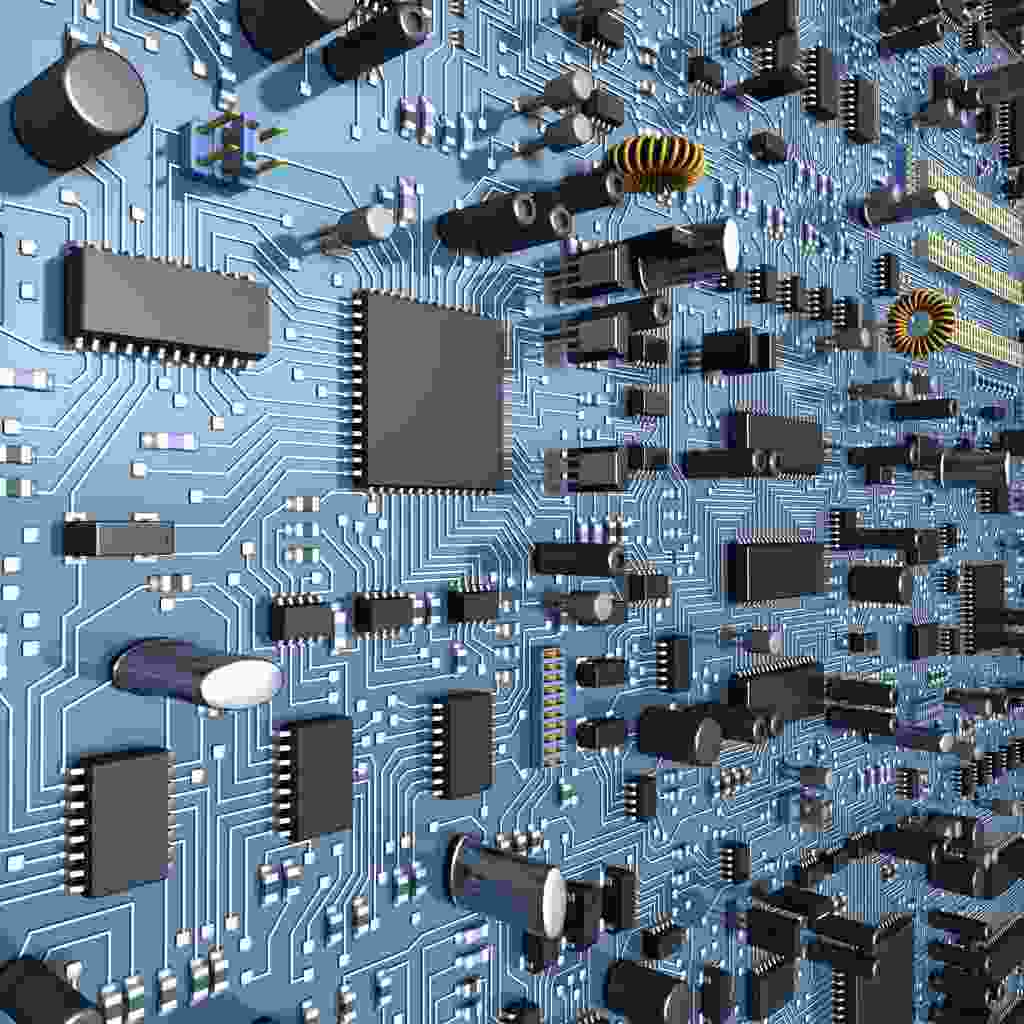
Solder paste printing: since the tray is equipped with a Flexible circuit board, there is a high temperature resistant adhesive tape on the flexible circuit board for positioning, and the height is not consistent with the tray plane, so an elastic scraper must be used for printing. The composition of solder paste has a great impact on the printing effect, so it is necessary to select the appropriate solder paste. In addition, method B needs to be used for special treatment of printing templates.
Installation equipment: First, solder paste printing machine, the printing machine should be equipped with optical positioning system, otherwise the welding quality will be greatly affected Secondly, the FPC is fixed on the tray, but there are always some small gaps between the FPC and the tray. What is the biggest difference from the PCB substrate Therefore, the setting of equipment parameters has a great impact on printing effect, placement accuracy and welding effect Therefore, FPC placement requires strict process control
EffICiency SMT patch processing has many aspects For example, if the total output is unchanged, the SMT chip production line has a large number, and the production speed can also be improved However, operating costs are also increasing Nowadays, the fierce competition in the electronic industry is unimaginable In the case of existing production lines, it is crucial to improve the placement rate and win customer satisfaction
Features: The processing precision of the chip is not high, and the number of components is SMAll. The components are mainly resistors and capacitors, or there are individual special-shaped components.
Key processes:

2. SMT processing during placement: Generally, manual placement can be used, and single components with higher position accuracy can also be placed by manual placement machine
3. Welding: Reflow welding is generally adopted, and spot welding can also be adopted under special circumstances.
High precision placement in SMT processing
Features: The FPC must have the positioning MARK of the base plate, and the FPC itself must be flat. In large-scale production, it is difficult to fix FPCs and ensure consistency, which requires high equipment. In addition, it is difficult to control the printing paste and placement process.
Key processes: 1. FPC fixation: fixed on the tray from printing patch to reflow soldering. The pallet used requires a smaller coefficient of thermal expansion. There are two fixing methods, and the placement accuracy is QFP lead spacing 0. Use this method when 65MM or larger
A. When the placement accuracy is QFP guide spacing 0. 65MM or less
B Method A: Set the pallet on the positioning template. FPC is fixed on the tray with a thin high temperature resistant adhesive tape, and then the tray is separated from the positioning template for printing. The viscosity of high temperature resistant tape shall be moderate, easy to peel after reflow welding, and there shall be no adhesive residue on FPC.
Solder paste printing: since the tray is equipped with a Flexible circuit board, there is a high temperature resistant adhesive tape on the flexible circuit board for positioning, and the height is not consistent with the tray plane, so an elastic scraper must be used for printing. The composition of solder paste has a great impact on the printing effect, so it is necessary to select the appropriate solder paste. In addition, method B needs to be used for special treatment of printing templates.
Installation equipment: First, solder paste printing machine, the printing machine should be equipped with optical positioning system, otherwise the welding quality will be greatly affected Secondly, the FPC is fixed on the tray, but there are always some small gaps between the FPC and the tray. What is the biggest difference from the PCB substrate Therefore, the setting of equipment parameters has a great impact on printing effect, placement accuracy and welding effect Therefore, FPC placement requires strict process control

抖音二维码

Q Q二维码

微信二维码
点击
然后
联系
然后
联系
电话热线
13410863085Q Q

微信

- 邮箱